8.7. 3D dislocation loop
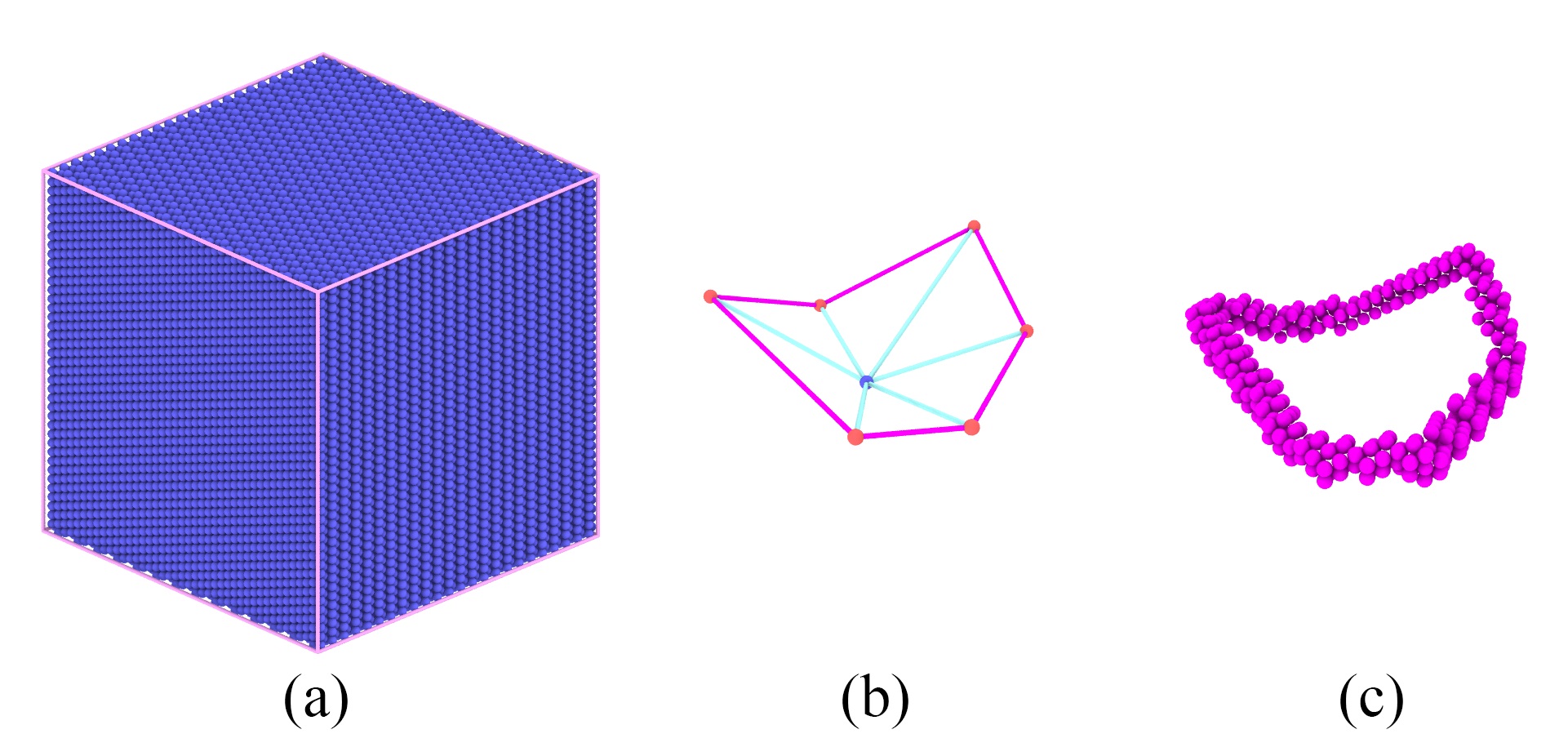
( a ) a single crystal BCC Fe sample. ( b ) Triangulation mesh grid of a surface in 3D space, and pink lines are the profile of the plane. ( c ) A 3D dislocaiton loop was constructed based on geomertrical surface in ( b ).
As shown in abvoe figure, by using a mesh grid data file, we could construct a 3D dislocation loop in crystal. The steps are given as follows:
Step 1:
Use the tool in the subdirectory tools/Bcc to creat an BCC single crystal sample by running the following command in Terminal. This will produce an ASCII text file of the atomic structure in current directory:
bcc_reg.lmp. Use the tool in the subdirectory tools/3DLoop to to create the mesh of a 3D surface:3dLoop.mesh
1#bash
2Bcc 100 100 100 -x 1 -1 0 -y 1 1 -2 -z 1 1 1 Fe
3
4#bash
53DLoop -c 0 0 0 25 6 13
Step 2:
Open terminal, run the following command:
1CryDisGen para_file bcc_reg.lmp
Parameter file
Content of the para_file:
 1#lines starting with '#' are comments
 2#crystal region definition
 3Region
 4-x      1 -1  0      # lattice orientation along x-axis
 5-y      1  1 -2      # lattice orientation along y-axis
 6-z      1  1  1      # lattice orientation along z-axis
 7-lat    2.866        # lattice constant
 8-pbc    1  1  1      # boundary condition flags along x/y/z-axes: '1' for periodic, '0' for non-periodic
 9
10nHelix 1
11Helix
12-bvh   1  1  1
13-bsh   1/2
14-f     3dLoop.mesh