8.5. Dislocation helix with a loop
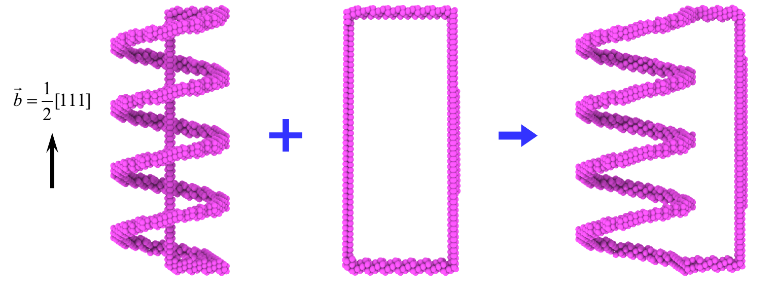
To create a dislocation helix combined with a loop,
Step 1:
Use the tool in subdirectory tools/Bcc to creat a BCC crystal sample:
bcc_reg.lmp, use the shell script in subdirectory tool/Helical_surface to create the mesh of a helical surface:mesh.dat;
Step 2:
Open terminal, run the following command:
1CryDisGen para_file bcc_reg.lmp
Parameter file
Content of the para_file:
 1#lines starting with '#' are comments
 2#crystal region definition
 3Region
 4-x      1 -1  0      # lattice orientation along x-axis
 5-y      1  1 -2      # lattice orientation along y-axis
 6-z      1  1  1      # lattice orientation along z-axis
 7-lat    2.867        # lattice constant of Fe
 8-pbc    1  1  1      # boundary condition flags along x/y/z-axes: '1' for periodic, '0' for non-periodic
 9
10nHelix  1
11Helix
12-bvh    1  1  1
13-bsh    1/2
14-f      mesh.dat
15
16#dislcoation
17nLoop    1           # number of dislocaiton loops
18Loopn                # label for dislocation loop section
19-bv     1  1  1      # orientation of Burgers vector
20-bs    -1/2          # scalar coefficient of Burgers vector, e.g., 1/2 in 1/2<110>
21-dnorm  1 -1  0      # normal direction of dislocation plane
22-dc     0  25 0      # center of dislocation loop
23-dr     25           # half of the edge length of a square loop
24-lx     1  1 -2      # local x-axis on the dislocation plane
25-ly     1  1  1      # local y-axis on the dislocation plane
26-ndisl  4  2.4       # number of segments/vertices in the square loop and a scaling factor
Important
In this example, the parameter tag ‘-ndisl’ accepts two arguments. When only a single argument is specified, the resulting dislocation loop assumes a square geometry. If a second argument is provided, it serves as a scaling factor for the loop edge oriented along the direction defined by the ‘-ly’ tag, thereby enabling the generation of rectangular loop configuration.