8.12. Straight edge dislocation
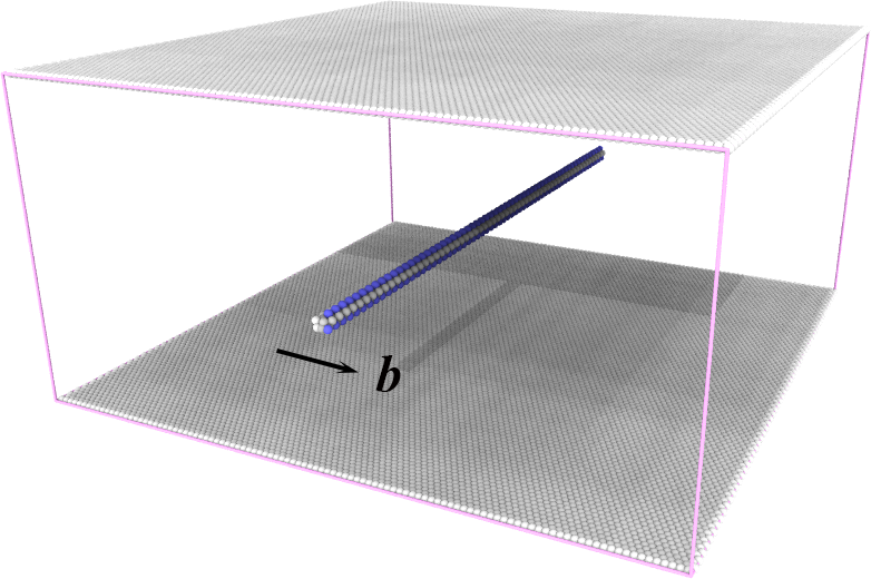
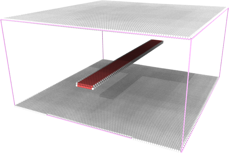
A straight edge dislocation is created in a single-crystal aluminum sample: the unrelaxed configuration ( left ) and the relaxed configuration ( right ). In the figures, atoms in perfect FCC lattice are not shown for clarity. White atoms are those at free surface and dislocation core, and red atoms are those in HCP lattice.
Note
To create a straight edge dislocation, one approach is to generate a pure edge dislocation loop with a square shape in a way similar to that of generating an intrinsic Frank dislocation loop. However, instead of removing a {111} atomic plane, two adjacent {110} atomic planes are deleted in present case. By scaling and positioning the square dislocation loop so that only a portion of the edge lies within the crystal region, an strainght edge dislocation can be inserted after applying the displacement field of the dislocation.
To create a straight edge dislocation withing a single-crystal aluminum sampel, the following two steps are employed:
Step 1:
Use the tool in the subdirectory tools/Fcc to creat an FCC single crystal sample by running the following command in Terminal. This will produce an ASCII text file of the atomic structure in current directory:
fcc_reg.lmp.
1Fcc 300 300 150 -x 1 -1 0 -y 1 1 -2 -z 1 1 1 Al
Step 2:
Open terminal, run the following command:
1CryDisGen para_file fcc_reg.lmp
Parameter file
Content of the para_file:
 1#lines starting with '#' are comments
 2#dislocation loop is on the local xoy coordinate plane
 3#crystal region definition
 4Region
 5-x      1 -1  0      # lattice orientation along x-axis
 6-y      1  1 -2      # lattice orientation along y-axis
 7-z      1  1  1      # lattice orientation along z-axis
 8-lat    4.05         # lattice constant
 9-pbc    1  1  0      # boundary condition flags along x/y/z-axes: '1' for periodic, '0' for non-periodic
10
11#dislocation
12nLoop 1
13Loop
14-bv     1 -1  0      # orientation of Burgers vector
15-bs     1/2          # scaling coefficient of Burgers vector, e.g., 1/2 in [110]/2
16-dnorm  1 -1  0      # normal direction of dislocation plane
17-dc     0  0  80     # center of dislocation loop
18-dr     180          # radius of dislocaiton loop
19-lx     1  1 -2      # local x-axis on dislocation plane
20-ly     1  1  1      # local y-axis on dislocation plane
21-ndisl  4  0.5       # number of segments/vertices in a discretized dislocation loop and a scaling factor
Important
In this example, the parameter tag ‘-ndisl’ accepts two arguments as well, and the second argument is a scaling factor used to scale the edge length of the dislocation loop along the defined direction specified by the ‘-ly’ tag.