8.11. Straight screw dislocation
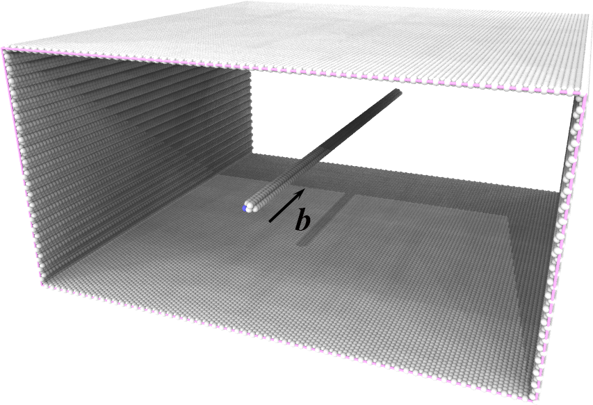
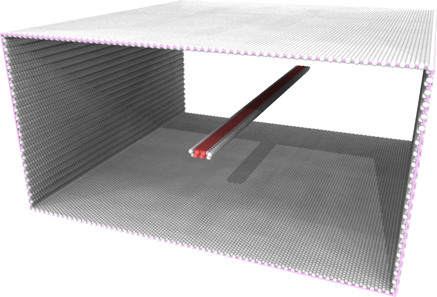
A straight screw dislocation is created in a single-crystal aluminum sample: the unrelaxed configuration ( left ) and the relaxed configuration ( right ). In the figures, atoms in perfect FCC lattice are not shown for clarity. White atoms are those at free surface and dislocation core, and red atoms are those in HCP lattice.
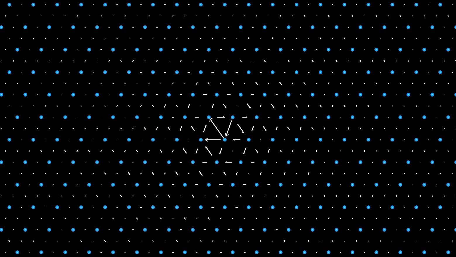
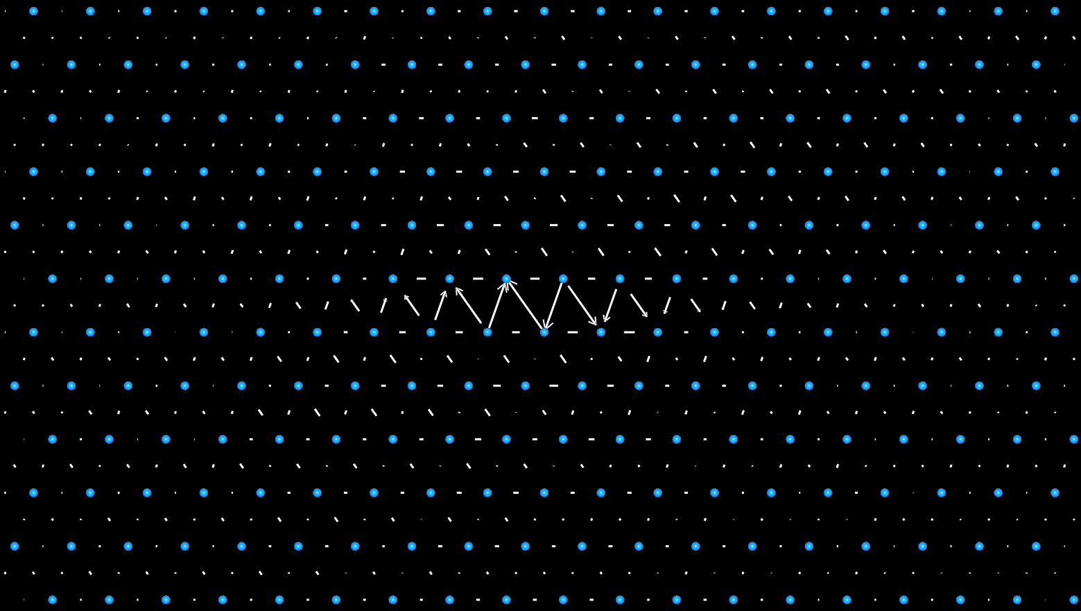
The core structures of the unrelaxed ( left ) and the relaxed ( right ) screw dislocations in aluminum, corresponding to the atomic models in the top figures.
Note
To create a straight dislocation, one approach is to define a larger dislocation loop—at lease one dimension larger than the crystal sample—in the parameter file. By appropriately scaling and positioning the dislocation loop so that only a portion of one edge resides within the crystal domain, a straight dislocation can be successfully introduced into the sample after applying the associated displacement field of the dislocation loop.
To create a straight screw dislocation in a single-crystal aluminum sample, the following two steps are employed:
Step 1:
Use the tool in the subdirectory tools/Fcc to creat an FCC single crystal sample by running the following command in Terminal. This will produce an ASCII text file of the atomic structure in current directory:
fcc_reg.lmp.
1Fcc 300 300 150 -x 1 -1 0 -y 1 1 -2 -z 1 1 1 Al
Step 2:
Open terminal, run the following command:
1CryDisGen para_file fcc_reg.lmp
Parameter file
Content of the para_file:
 1#lines starting with '#' are comments
 2#dislocation loop is on the local xoy coordinate plane
 3#crystal region definition
 4Region
 5-x      1 -1  0      # lattice orientation along x-axis
 6-y      1  1 -2      # lattice orientation along y-axis
 7-z      1  1  1      # lattice orientation along z-axis
 8-lat    4.05         # lattice constant
 9-pbc    1  0  0      # boundary condition flags along x/y/z-axes: '1' for periodic, '0' for non-periodic
10
11#dislocation
12nLoop 1
13Loop
14-bv     1 -1  0      # orientation of Burgers vector
15-bs     1/2          # scaling coefficient of Burgers vector, e.g., 1/2 in [110]/2
16-dnorm  1  1  1      # normal direction of dislocation plane
17-dc     0 -100 0.5   # center of dislocation loop
18-dr     200          # radius of dislocaiton loop
19-lx     1 -1  0      # local x-axis on dislocation plane
20-ly     1  1 -2      # local y-axis on dislocation plane
21-ndisl  4  0.5       # number of segments/vertices in a discretized dislocation loop and a scaling factor
Important
In this example, the parameter tag ‘-ndisl’ accepts two arguments. When only a single argument is specified, the resulting dislocation loop assumes a square geometry. If a second argument is provided, it serves as a scaling factor for the loop edge oriented along the direction defined by the ‘-ly’ tag, thereby enabling the generation of rectangular loop configuration.